Bruner control strip is a quality inspection tool recommended by China's printing standards. It is used for measurement and calculation of field density, dot gain, dot distortion, and print contrast (K value) for proofing and printing. It can also be used for visual inspection. At present, most of the latest control bars with 7 control segments are used, but in practice The most commonly used print is the Brunel three-segment test strip (Figure 9-1). The following focuses on its role and use.
The role of a solid patch segment (1) Measurement of the proofing, the density of the printed field and the degree of ink ink.
(2) Measure and calculate the three major characteristics of three primary color inks, namely color shift, gray scale and efficiency.
The best field density value for controlling four-color inks is not only the core of color proofing for proofing and printing data, but also the core of data color management in the entire copying process. The picture shows that the solid density (ink layer thickness) has a great influence on the quality of proofs and prints. If the density is too large in the field, the dots will increase, the prints will be rough, and the density in the field will be too small. Therefore, the color saturation is insufficient. Therefore, the best spot must be achieved. Specifically, the optimal field density is 75% to 80%. The value of the maximum field density achieved when the outlets increase to a minimum or within a reasonable increase range. That is, the solid density at the maximum K value is the best solid density because the thickness and density of the ink layer have a close relationship as measured by a reflection densitometer. The absorption characteristics of the ink layer depend on the ink hue, the ink layer thickness, and the ink. The nature and density of the colorant.
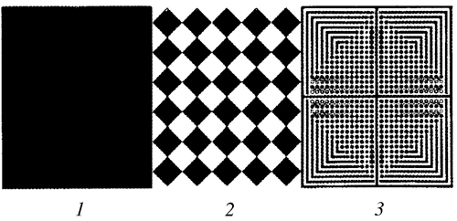
Figure 9-1 Bruner's Three-Stage Test Strip
For the representative proofing, the field density range of the printed wet ink layer is shown in the table. In the actual proofing and printing process, not only must all process and technical measures be used to achieve the best field density value, but also the consistency of the density on the ground, such as proofing, must be consistent with the four-color density of five standard proofs. To achieve consistent left, middle, and right densities, the error is ±0.05D. In the printing, a product and a print are to be made, and the ink color from the start printing to the halfway through to the final printing is the same, which needs to be measured by controlling the conditions and the density meter to obtain.
Table 9-1 Proofing, printing wet ink layer field density range of different substrates CMYK
Coated paper 1.6 1.45 1.35 1.90
Asian powder paper 1.6 1.45 1.35 1.90
Writing paper 1.35 1.25 1.10 1.45
Newsprint 1.00 0.95 0.75 1.10
Note: The table value ±0.05 is the solid density range
Two 50% coarse network segments
The 50% thick section consists of 10 lines/cm dots with 50% dot area. Its main function is:
(1) Visually observe changes in dot gain and decrease directly.
(2) Calculate the increase of the 50% dot.
In actual production, operators often observe changes in the 50% coarse network segment, and use this to determine changes in network points, the general network points increase, 50% of the coarse network segment must take a serious angle, otherwise, the network spacing increase Large, the outlets decrease.
The above-mentioned dot gain value formula is of universal significance, and the calculation of the increase value of the 50% dot zone is based on the principle of the relative proportion of coarse and fine dots and is based on the principle that the total area of ​​coarse and fine dots is equal. The ratio of lines is 1:6, that is, the perimeter of a 50% fine mesh is 1/6 of the coarse mesh. The circumference of a row of 6 fine mesh points is equal to the circumference of a coarse mesh point. The sum of the 6 rows of fine dots is 6 times the coarse dots. Therefore, under the same conditions, the increase of fine meshes is very large. Therefore, based on the 50% thick mesh segment, taking the difference between the density of coarse and fine, the increase value of proofing and printing 50% dot area can be obtained. .
50% increase in dot area = (fine segment density - coarse segment density) × 100%
If the measured density of the 50% coarse mesh segment is 0.30, the density value of the 50% fine mesh area is 0.45, and the increase value of the 50% mesh area is substituted into the formula = (0.45-0.30) x 100 = 15%
This method is simple and accurate and is suitable for on-site management.
Three fine dot micro measurement segments
The fine-mesh micromeasurement section, also called the ultra-micro measurement element, is the core part of Bruner's system (Figure 9-2). The thin network segment is composed of 60 lines/cm isobaric lines, and the total network area is 50%. The fine network segment divides the fine network area into four with equal width and large cross lines. The formation of 1/4 area dot is exactly the same. But in different directions, its main functions are as follows:
Figure 9-2 Magnification of the 50% fine mesh
(1) The outer corner of each 1/4-grid is composed of a 6-line/mm isosceles fold line, which is used as a check for whether there is any sliding deformation or ghosting of the dots during printing. If the four corner lines of the proof are deformed, it indicates that the printed dots have slipped. Lateral sliding, the vertical line becomes thicker, longitudinally sliding, horizontally thicker.
(2) There are 13 outlets in the first row near the reticle, and a row of outlets on the inside is a small black point from large to small, and the next one corresponds to 12 small black dots from large to small. Corresponding to it are 12 hollow white dots from large to small, which are 0.5%, 1%, 2%, 3%, 4%, 5%, 6%, 8%, 10%, 12%, 15 respectively. The % and 20% positivity points correspond to the shade points.
Judging the variation of printing, proofing and printing outlets, 25 times magnifying glass can be used to observe. For example, using PS printing and drying out 10 small black spots, 2% of small outlets are complete. The standard exposure and development of the printing plate should reach the yin and yang points. During the proofing and printing, under the condition of no density meter, the data can be visually enlarged (as shown in Figure 9-3), and the small white hole is observed to have several translucent colors, indicating how much the dots are increased. If the 12 small white holes leave a few translucent, it indicates how much the dots increase. If 12 small white holes are completely stuck, the network will increase by 20%. If 10 small white wells are left dead, 2 small white holes are left, indicating that the outlets are increased by 15%; there are 4 small white holes, indicating that the outlets are increased by 10%. The general proofing specification should retain 4 small white holes.
3 There are 4 50% standard square points in each 1/4 block, which are used to control the depth and depth of layout during printing, proofing and printing. If 50% of the standard squares have large angles, then the dots will increase. If the squares are separated, the dots will shrink.
Figure 9-3 Increase or decrease the visual spot
Source: Seal
Key words to describe our clipping machines: high-capacity automatic clipper,semi-automatic clipper,single table clipper,automatic double clipper,connected to the filler, for closing sausages in natural or artificial casing with two aluminum clips.
We provide our customers whole clipping machine series, including the automatic double clipping machine, semi-automatic single clipping machine and table manual clippers. Our clipping machines can work well with Great wall shape clips (similar with polyclips R clip series), U shape clips, and aluminum wire directly. Thanks to our professional technical team, our automatic double clippers are featured with neat structure, fast speed, low noisy, easy cleaning and simple maintenance.

Sausage Packaging Machine,Manual Sausage Clipper,Clipping System Solutions,Semi-Automatic Clipper,Single Table Clipper,Automatic Double Clipper
Helper Machinery Group Co., Ltd. , https://www.helperfoodsolution.com